
Modification tracking in a Revit model is a recurrent topic. It’s always very time consuming to compare different versions of the same model, and to figure out what’s new, what was deleted, and what has changed.
A little online research pointed me, as often, to a post from Jeremy Tammik on the building coder. In his post, he describes two approaches to the problem. One of these aproaches is to compare “snapshots” of models. His work inspired me to create a couple of dynamo nodes and workflows to facilitate the fastidious task of modification tracking!
The goal was to create an easy way to figure out what modifications occured between two versions of the same model and to offer an easy way to visualize those modifications. I will first introduce the set of nodes I came up with then I’ll develop about how they can be used in three separate workflows.
1. The Nodes:
1.1 ModificationTracker.ModelComparison: This node is the first step of the modification tracking. It takes 3 inputs :
- DocumentA : Current document by default.
- DocumentB : The document you want to compare DocumentA against.
- Categories : List of categories you want the ModificationTracker to take into account
The code of this node uses the elements’ GUIDs to determine whether they are existing, new or deleted. It will return a report of the modifications and lists of the existing, new and deleted elements. The ExistingElements Data output is the data you’ll need to initiate the geometry and metadata comparisons between DocumentA and DocumentB.

1.2 ModificationTracker.GeometryChanges: This node compares meshed approximations of the geometry of elements that exist in both DocumentA and DocumentB. It will then output the elements with the same geometry and those with a modified geometry in separate lists.

Here are the definitions I used to get the geometry “Snapshots”:
This file contains bidirectional Unicode text that may be interpreted or compiled differently than what appears below. To review, open the file in an editor that reveals hidden Unicode characters.
Learn more about bidirectional Unicode characters
| #Copyright (c) mostafa el ayoubi , 2016 | |
| #Data-Shapes http://www.data-shapes.net , elayoubi.mostafa@gmail.com | |
| #This code was inspired by Jeremy Tammik @Jeremytammik | |
| def flatten(container): | |
| for i in container: | |
| if isinstance(i, (list,tuple)): | |
| for j in flatten(i): | |
| yield j | |
| else: | |
| yield i | |
| def tostring(x): | |
| return x.ToString() | |
| def getgeomlist(x): | |
| return list(x.get_Geometry(Options())) | |
| def getvertices(x): | |
| #getting geometryelements as list | |
| geomelems = getgeomlist(x) | |
| #getting nested instance geometry for all geometry instances | |
| while any('GeometryInstance' in g for g in map(tostring,geomelems)): | |
| for index,i in enumerate(geomelems): | |
| if 'GeometryInstance' in i.ToString(): | |
| geomelems[index] = i.GetInstanceGeometry() | |
| else: | |
| continue | |
| geomelems = list(flatten(geomelems))[0] | |
| #getting all faces, keeping meshes | |
| faces = [] | |
| for i in geomelems: | |
| if 'Solid' in i.ToString(): | |
| faces.append(list(i.Faces)) | |
| elif 'Mesh' in i.ToString(): | |
| faces.append(i) | |
| else: | |
| continue | |
| faces = list(flatten(faces)) | |
| #getting all meshes | |
| meshes = [] | |
| for f in faces: | |
| if 'Mesh' in f.ToString(): | |
| meshes.append(f) | |
| else: | |
| meshes.append(f.Triangulate()) | |
| #getting all vertices | |
| vertexlist = [] | |
| for m in meshes: | |
| vertexlist.append(list(m.Vertices)) | |
| vertexlist = list(flatten(vertexlist)) | |
| #creating sorted vertex string representation of object for comparison with other indice of element | |
| vertexstr = ', '.join(sorted(set(map(tostring,vertexlist)))) | |
| return vertexstr |
1.3 ModificationTracker.ParameterChanges: This node compares string “Snapshots” of the parameters of the elements that exist in both DocumentA and DocumentB. Like the GeometryChanges node, it will return changed and unchanged elements in separate lists.

Here is the definition I used to get the parameter values “Snapshots”:
This file contains bidirectional Unicode text that may be interpreted or compiled differently than what appears below. To review, open the file in an editor that reveals hidden Unicode characters.
Learn more about bidirectional Unicode characters
| #Copyright (c) mostafa el ayoubi , 2016 | |
| #Data-Shapes http://www.data-shapes.net , elayoubi.mostafa@gmail.com | |
| #This code was inspired by Jeremy Tammik @Jeremytammik | |
| def parametersnapshot(x): | |
| parameters = x.Parameters | |
| paramnames = [p.Definition.Name for p in parameters] | |
| #Sorting is important because the parameters are queried in random order. | |
| #We need to make sure the snapshots are ordered in the same way so we can compare them. | |
| sortedindex = sorted(range(len(paramnames)), key = lambda k : paramnames[k]) | |
| sortedparameters = [paramnames[i] for i in sortedindex] | |
| paramvalues = [] | |
| for p in parameters: | |
| if p.AsString() != None: | |
| paramvalues.append(p.AsString()) | |
| else : | |
| paramvalues.append(p.AsValueString()) | |
| sortedvalues = [paramvalues[i] for i in sortedindex] | |
| return ', '.join(['%s : %s' % (param,value) for param,value in zip(sortedparameters,sortedvalues)]) |
1.4 ModificationTracker.AllChanges: This node compares both the geometry and the parameters of the elements that exist in two versions of the same model:

2. The Workflows
These nodes were created to serve the following workflows (I make use of UI.MultipleInputForm++ and Dynamo Player in order to make them as user friendly as possible ) :
Important note: The ColorSelection input in the form is only available with revit 2017. You will have to set the color overrides whithin the script if you are using Revit 2016 or a previous version.
2.1 Visualize geometry changes:
This workflow will prompt the user to select the linked model to compare the current model against, the cotegories to track and the override colors for changed, unchanged, and new elements.

To test this workflow, I have created a “Dummy” Revit file with some walls and colums, then I moved some of these columns and walls and saved it as a new version. I have tried the workflow on a “real” model with over 2000 elements and the performance was still pretty good.

2.2 Vizualise parameter value changes:
This workflow works in a very similar way to the previous one except it tracks parameter value modifications instead of geometric modifications.

As a test, I have two versions of a same model where only some text parameter values have been changed on a wall and two columns.

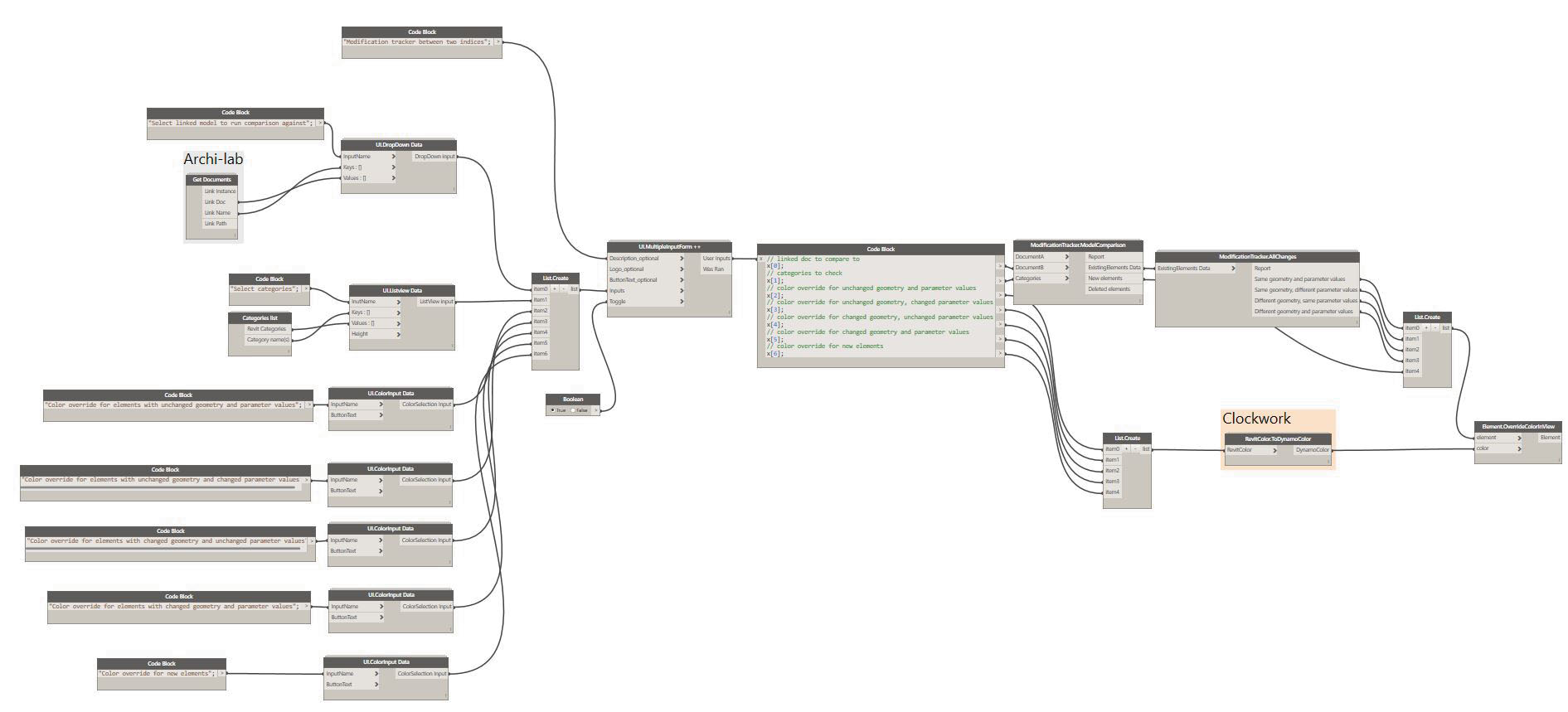
2.3 Vizualise geometry and parameter value changes:
This workflow allows to track parameter value changes as well as geometric changes. It creates a form that prompts the user to select the linked file to take into account, the categories, and all the override colors.

Please let me know if you’re facing any issues with those nodes. I’d be happy to improve them!

These look very useful. I assume the intent is that Document B would be an “archived” copy of the same model saved earlier? I envision comparing two linked mechanical models – an older version that I used to coordinate electrical connections and the current linked version. Since I work directly in neither they would both be linked. Can’t wait to give them a try.
LikeLiked by 1 person
Hi Scott,
yes that’s right. “Indice” might not be the propper term in english. But the idea is exaclty what you describe.
Also, while the nodes will give you the lists of changed/unchanged elements between two linked models, you won’t be able to override their color in a view. To my noweledge, this can only be done with the current model. I would be very happy if someone proves me wrong about this! 🙂
I’d be very interested to know how they work for you.
LikeLike
Hi Mostafa,
I use both Revit 2016 and 2017 and was trying your “Model checker all workflows” graph (un-modified) in 2016 and received a “dereferencing a non pointer” error at the Element.OverrideColorInView node.
I created two detached mechanical models, modified one and linked the unmodified one into the “new” version and ran the graph within the new version of the model.
Thoughts?
Thanks much,
Scott
LikeLike
This is due to something that was pointed out by Cesare Caoduro today . The ColorSelectionDialog is not exposed in 2016. I updated the package today to handle that exception. You should be able to use the script with no problem in Revit 2017, but you won’t be able to have the color selection buttons on the form with Revit 2016. Also, is your Revit language english?
LikeLike
Hi Mostafa,
Awesome work!
I’m using Revit 2017 and I’m still experiencing this issue even though I downloaded your package update from today. I received a “dereferencing a non pointer” error at the Element.OverrideColorInView node.
Cheers! Thank you so much for your work!
Brice
LikeLiked by 1 person
Thanks for the quick reply – yes – English.
LikeLike
Thanks for the kind words Brice!
Could you please post a screenshot of the output of UI.MultipleInputForm++ on the github repository ( https://github.com/MostafaElAyoubi/Data-shapes ) or on the dynamo forum so I can have a closer look at it? I really appreciate the feed back!
LikeLike
I just tried in 2017 also and received the pointer error and a message of a video driver error then Revit closed.
LikeLike
Scott, can you please post a screenshot of the output of UI.MultipleInputForm++ on the github repository ( https://github.com/MostafaElAyoubi/Data-shapes ) or on the dynamo forum so I can try and figure out the reason and the issue?
LikeLike
Really nice work! This was on my list of nodes to create so eager to give them a spin. Loving the Dynamo Player friendly UI.
LikeLiked by 1 person
Excellent work Mostafa! For previous version of revit what package i need to trigger the colour overrideS?
LikeLiked by 1 person
Hi Ioannis,
Thanks! 🙂 You could use OOTB color.ByRGB node or Clockwork that hase some colors already set.
LikeLike
Thanks for the response! Not sure OOTB colo.ByRGB node is? Is it from a package?
Would it work with the color picker from rhythm of John Pierson for earlier versions?
Also from a revit perspective GUID is rather unstable with different versions, Would i have to change any script to switch to element ID?
Once again you are bringing cutting edge stuff to the masses thanks a lot Mostafa!!
LikeLiked by 1 person
I have tried clockworks nodes which are the one you use but no effect 😦
What can I feed to the geometry colour change codeblock?
I ll do later a post on the forum
LikeLiked by 1 person
Rather randomly I got it to work. Sorry for overflowing your comments, but i find it extremely intresting.
Anyway Ican add deleted elements as well in the geometry workflow?
thanks
John
LikeLiked by 1 person
Hi John, thanks for you comments
if the deleted elements are in the linked file, you won’t be able to override their graphics. As far as I now, this cannot be done through the Revit API. Glad you got the colors to work. John Piersons ColorPicker works with the same method I used so you wont be able to use in a version of revit older than 2017. What you can use though is the color picker from UI++ package . Don’t hesistate to ask on the forum if you need help !
LikeLike
My name is Lewis Kent I am a BIM manager at a Large Contractor and this is the perfect tool for me, will save me and my company alot of time and cost. I am a new to Dynamo could you please advise me how to go about getting this up and running tutorials etc i will need to get myself up to speed and become able to create manipulate this script to my projects.
I thank you in advance for even creating this any further assistance will be humbly received.
LikeLiked by 1 person
Hi Lewis,
thanks for your comment, saving people time and money is exactly the purpose of that kind of work 🙂 Very glad you think it can do that for you.
The wrokflows I described in the article are pretty much ready to use, you can download the .dyn file (pick the right one according to the version of revit you’re using) and open it with dynamo1.2 and you should be able to use it as described. If you face any issue I’d be happy to help, just ask on the dynamo forum.
LikeLike
Hi Mostafa,
Wow! Good idea, good implementation. Discoverd this tool just this week. Up to now, I hit one snag; the ModificationTracker.AllChanges tool does not seem to recognize an added parameter. Am I correct in assuming that for still-existing elements, it only checks parameter values for parameters that existed in the families in the original file?
Still, the .ModelComparison does the heavy lifting, I think I can take it from there.
Thanks!
LikeLiked by 1 person
Hi Ekko Nap,
thanks for your comment. You’re correct if a parameter is added the nodes will consider that the parameters have changes, even if all the existing parameters are the same. I will try and find a way to handle thoses cases better. Thanks for the feedback!
LikeLike
Could you please give the names of the packages needed to run this script.
Thank you
LikeLiked by 1 person
Hi Lewis ,
You’ll need clockwork, archi-lab and data-shapes .
LikeLike
Hi is there a reason when i run this all i get is an empty form? i get headings but no input locations/prompts
LikeLike
Please update to 2017.2.2 , I have removed the screen resolution part handling as it seems to not function correctly in some conditions.
LikeLike
Works Great now! thanks!
LikeLiked by 1 person
Hi Mustafa, Great job. I’m wondering if is possible also to track location changes with this workflow. at this point is the missing components for this great workflow… is it possible to track a change of location of a components that has been moved?
Thanks for your work
LikeLiked by 1 person
Hi Claudio ,
Thanks for your message. The elements that have been moved will be pointed at by ModificationTracker.GeometryChanges . Are you trying to only get those elements ?
LikeLiked by 1 person
Yes, i’m experiencing some troubles, with some columns placed at grids crosses. When you move one of them, the columns records a different value on the “Column Location” Parameter. So the nodes records a change in parameters but not on the location. There is any open tread on the Dynamo forum where i can post some screenshots, or in any other place on the web.
LikeLiked by 1 person
That sounds interesting. You should create a thread on the forum so we can further discuss the issue. Your feedback can help improve the tool or even lead to new ones!
LikeLiked by 1 person
Ok i’ll do it later tonight
LikeLike
Hi Mustafa,
Thank you, I am a BIM Team Leader and it’s very useful tool for me.
I just discovered in two days. I have got some issues with the Properties change.
I can not track the change of some instant parameter of system families (Material of wall, etc…) and some user type parameters (such as material of window frame, etc…) .
In the other hand, I have Solibri to track the change of IFC models. However, the feature to track the modification inside Revit is very great.
We have tried to make an add-in to track all changes inside Revit and your work with Dynamo is uesful reference for us to do that.
Hope we can share the ideas and knowledge.
Thank you again.
LikeLiked by 1 person
Hi Mostafa. Great work, fan of it. I just saw this methodology to check between models but I get and error in the Clockwork Node you use, so I can’t get the job done. Please check the Dynamo Forum, i’ve posted the related error.
https://forum.dynamobim.com/t/return-list-or-single-value-clockwork-package/10366
Thanks in advance!
LikeLiked by 1 person
Hi Jorge,
thanks for your message! I can’t find your topic on the forum. Could you share a link?
LikeLike
Hi mostafa, the link is: https://forum.dynamobim.com/t/return-list-or-single-value-clockwork-package/10366
Thanks!
LikeLike
Hi Mostafa,
I think, I am having similar issues. I have Revit 2018 and I get the “Non-Pointer” error.
https://forum.dynamobim.com/t/multi-input-ui-non-pointer-error/16238?u=archinecture
LikeLike
Hi Mostafa, I’m using your script ( check geometry only ) in revit 2016 and i can’t get teh UI menu to come up when i run dynamo.
Any idea why this might be happening.
Great work by the way and thanks in advance
Kind regards
LikeLiked by 1 person
Hi! Thanks for your message 🙂
First of all, make sure you’re using the .dyn for revit 2016. It’s different because Revit 2016 doesn’t support the color selection input of the form. The second thing you can do is right click on each input of the data-chapes nodes and make sure the default values are activated. This only needs to be done once. I should update the downloadable definition and fix that.. 🙂
LikeLiked by 1 person
I cannot seem to recreate the graphs so that they work in REVIT 2018.3. the codeblock after Multipleinputform++ fails as a Get.valueatindex operation failed « index out of range » error.
Any thoughts?
LikeLike
Please disregard my previous question. I figured out that I had some inputs that needed to be reset..again. I constantly get bit by this one by forgetfulness 🙂
Thank you for such a great Contribution!!
LikeLiked by 1 person
Hi!
I have same problem. What do you mean with « some inputs that needed to be reset »?
LikeLike
Dimitar
I believe the process is to select the placed node on the canvas, then right click to get the options. There is where you can “reset” the node, but I believe it has to have Thrown an error first before that option becomes available as I cannot get it to show on a correctly working node.
Sorry for such a long delay in the response!
LikeLike
Hi Mustafa (forgive my spelling),
This script works well when comparing old and new versions of an equivalent model. However, is there a node modification / script that performs a similar task, only between linked models comparing, say, architectural and structural models? My end goal is to track the same category from each model, compare them, and color/flag them visually if one of them changes / something is added.
LikeLike
I’d like your input on the feasibility of using this workflow to compare two views in the same model. The idea is to compare detail callouts for similarity in order to inform the placement of live vs reference callouts. Thoughts?
LikeLike
Hi Greg! Thanks for your message. That’s a good one. So the idea would be to run the comparison between elements in a specific view range VS elements circled by reference call outs?
LikeLike
Presumably the idea is to find similar locations in a model, referenced against a user indicated location and range (by means of selecting an existing View?), and place a View Reference in certain other Views?
Or would it be more feasable to compare Views to a user-input original and replace those Views with Reference Views where the Callouts were visible?
LikeLike